<<<
Brick Types
Atari Power Brick Troubleshooting
Visual Inspection
Now that you know what kind of power brick you have and have
pulled the schematics for it, now it’s time to do some basic troubleshooting. Take
a close look on, around, and under your power brick. Look for anything that
doesn’t look right such as burnt components, cut wires, wires pulled away from
their terminations, missing Power Selector, missing fuses (including pulling
the main fuse), or any Molex connectors that should be attached but aren’t.
Fuses
You will need you digital multimeter for this step. First we
want to check all of the fuses and make sure they’re ok. Set your multimeter to
‘continuity test’ and make sure your game is UNPLUGGED FROM THE WALL SOCKET. If
your brick has the paper shield covering the fuse block, carefully remove it.
Next, probe across each fuse in the fuse block as in Figure 1 and make sure
there’s continuity. Your meter should probably ‘beep’.
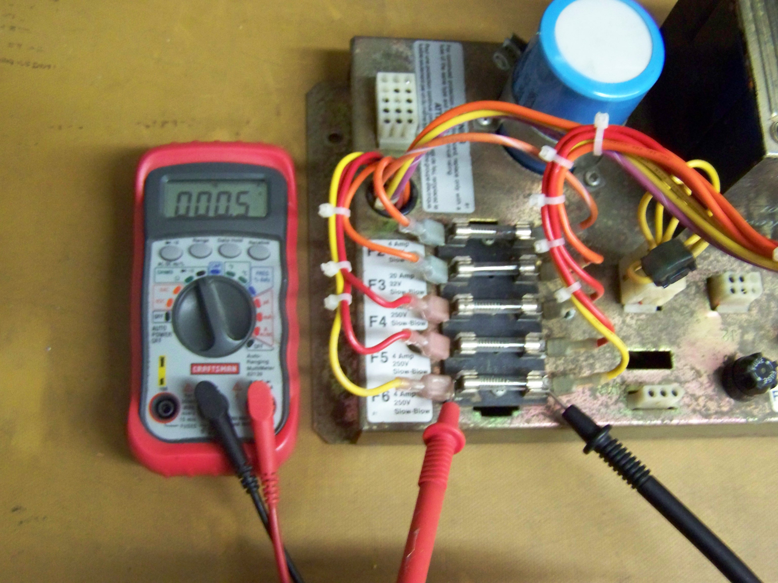
Figure 1: Continuity Test of Fuses
If you find one or more bad fuses you must replace them. The
fuse voltage and amperage ratings are listed on the fuse block. It is highly
recommended you use an exact rating replacement! Using anything else would mean
either you’re not allowing enough current to flow in the circuit and the fuse
will blow under normal operation, or you’re allowing too much current to flow
and you’re allowing the circuit fault downstream to destroy something.
Next, unscrew and pull the main fuse. Check for continuity
just like you did before. If it’s bad, replace it.
If you found just one bad fuse, you could now try to operate
the game and see what happens. Like other electronic components, fuses just
sometimes go bad. If you find more than one bad fuse then chances are it’s not
just the fuses that are bad. But in most cases the very worst that will happen
is you’ll blow the new fuses.
Molex Connector
Pinouts
Before we tackle the next section on testing voltages, we
first need to understand how Molex connectors are pinned. There’s two sides to
a connection pair – male and female. The male side has wire terminations that
are pins, primarily, while the female side has sockets as wire terminations. If
you look ahead to the Molex connector in Figure 3, you can see that the
connector has female socket terminations in all but two positions, so we can
refer to this end as female. It is important to note that pin numbering for
male and female connectors are exactly mirrored from each other. What I present
here are the female pin numberings. To get the male numberings, just
mirror the female numberings.
If your eyes are still good enough you can also look at the
insertion side of the connector and find the pin numbers stamped by each pin.
Figure 2 shows pinnings for some common Molex connectors while looking into the
female end of the connector.
Figure 2: Female Molex Pinouts
Testing Voltages
In this step we will be testing the voltage outputs from the
brick. Take a look at your schematic and find the reference designators for all
of the connectors. These refer to the Molex connectors on your power brick. For
example, on my schematic the 15-pin connector J5 refers to the Molex connector
J5 on the power brick.
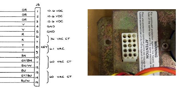
Figure 3: Molex Connector J5
Look closely and you’ll find that the reference designators are
stamped next to each Molex connector on the brick. We want to find the Molex
connector(s) that give voltages out of the brick. In this case we’ve found J5.
If you removed the power brick from the game, re-install it
and re-connect all of the Molex connectors except for the voltage output
connector J5. Notice that we have both AC and DC voltage outputs here. No
matter what type of brick you have, there are two main voltages that the Audio
Regulator (AR) board uses to power your main CPU board: 10.6VDC (or 10.3VDC)
and 36VAC. The rest of the voltages are used for things other than the CPU like
the marquee light, fans, monitor, etc. We want to make sure that all of the
voltages are good, but those two in particular.
Power your game on and set your multimeter to measure DC
volts. Carefully stick the positive (red) lead of your multimeter into one of
the 10.6VDC female pins. Then stick the ground (black) lead into one of the GND
female pins. You should measure close to 10.3VDC. The voltage is unregulated so
it might not be exact. If your reading is within about 20% then it should be
ok. There’s no need to test all three of the 10.3VDC outputs since they are all
tied together.
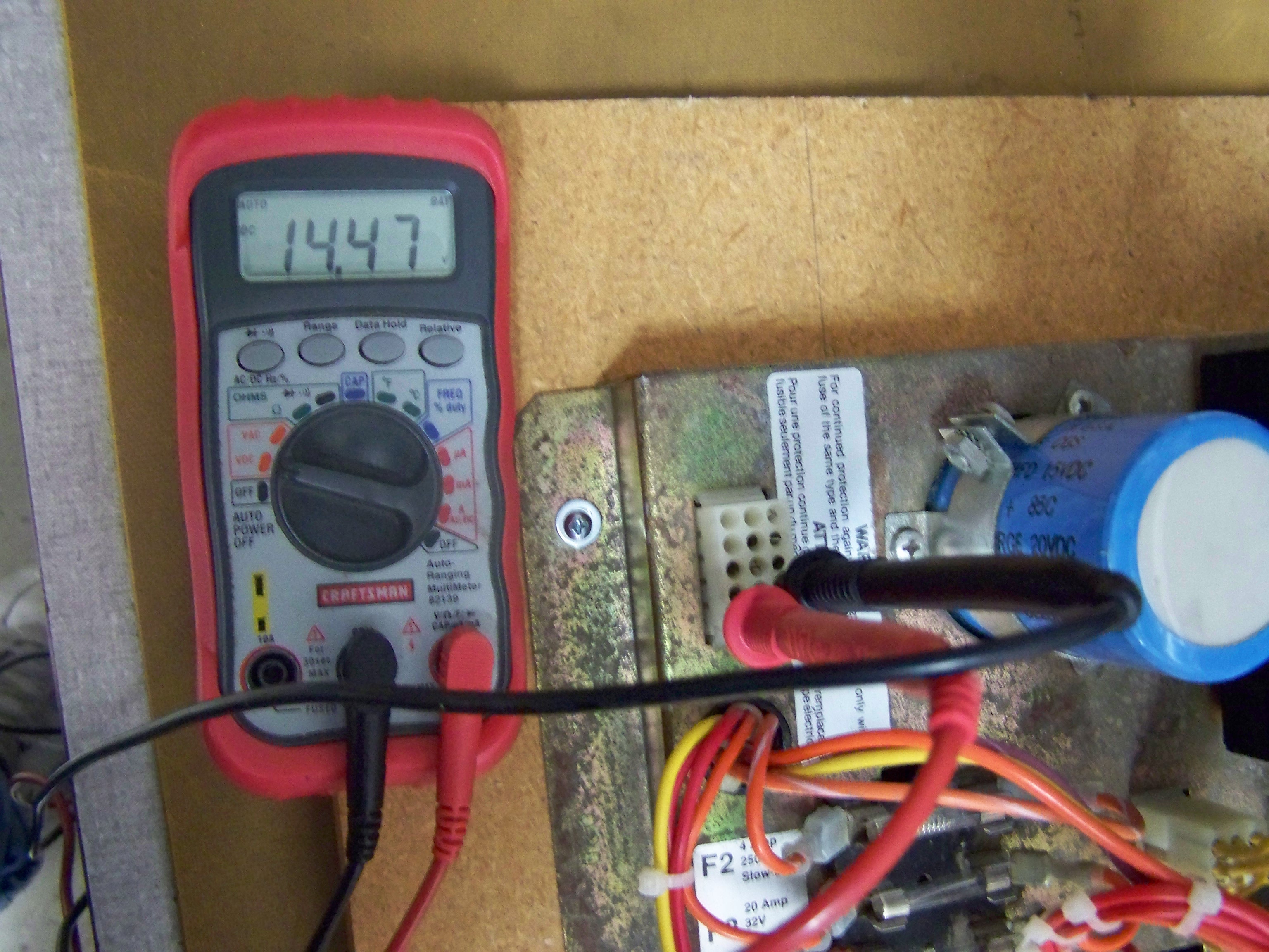
Figure 4: Testing Voltages
Remove the test leads from J5 and set your meter to measure
AC volts. Now before we measure AC volts we need to review briefly how a
transformer works. A transformer performs two basic functions. First, it is
able to change the output AC voltage less-than, greater-than, or the same as
the input AC voltage. Second, it serves to isolate the output AC from the input
AC so as to move the relative ground where it needs to be. The main thing to
remember is that a transformer center-tap will be at half the AC voltage of the
two ends. Let’s take our Centipede transformer as an example.
Figure 4: Centipede Transformer Schematic
Probing between pins 13 and 15 in this circuit yields 60
Volts AC. Probing between pins 13 and 14, or between 14 and 15 should yield
about 30 Volts AC. Continue testing all of the AC voltages on the voltage
output connector on your power brick. Refer to your schematic to make sure you
cover all of the voltages. If you find that pins are missing from the Molex
connector then don’t worry about testing those voltages.
If all of the voltages check out then it’s time to move on to
testing the Audio Regulator (AR) board.