Atari High
Score Save
Part 1: The
-30V Power Supply
Technology sure has come a long way. As evidence you don’t have to look much further than the old Electrically Alterable Read Only Memory (EAROM). As its name suggests, the EAROM allows an outside device such as a microprocessor to modify its memory contents and then holds the information like a Read Only Memory (ROM) even after power is removed. This was the technology Atari chose to save important information on their game boards during the arcade Golden Age.
One particular EAROM device you might find on Atari boards is the General Instrument ER2055. This device used memory cells with an oxide-nitride barrier. Upon a write from the chip’s external interface, the barrier would trap a charge that would persist even after power was removed from the device. In this way the EAROM could be used to save information such as high scores and other important data after the game was switched off at the end of the day. Of course these devices were slow and expensive compared to contemporary storage devices. One particular quirk about them was they required a -30V power supply in order to set the charge in a memory cell. This odd voltage must’ve proven awkward for Atari engineers since games like Centipede already had a multitude of other voltages coming in off-card. Fortunately the ER2055 required only a limited amount of current. The small current requirement made this voltage the ideal candidate for a voltage-doubler circuit, which is the route Atari chose.
Figure 1 shows one incarnation of Atari’s -30V power supply. The main components of the supply include the 555 timer circuit which generates a pulse train, the AC-coupling capacitor, the blocking diodes, and the charge pump capacitors. The 555 timer device is shown in an astable configuration which will generate a +15V pulse train at about 7 kHz and 70/30% duty cycle. Figures 2 through 5 show oscilloscope waveforms at various points of interest in the timer circuit. Note that the oscilloscope is using 10X probes, so that a 500mV deflection actually refers to a 5V change. In all screenshots, ground is referenced at the vertical centerline.
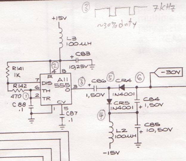
Figure 1: -30V Power Supply on Centipede
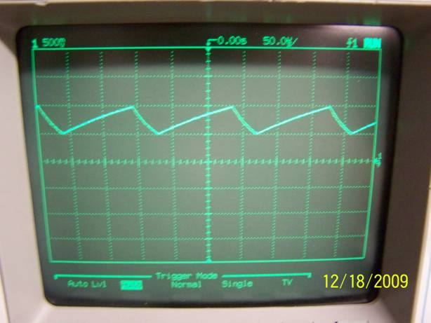
Figure 2: Point #1, the R-C Threshold
Trigger for the 555 Circuit
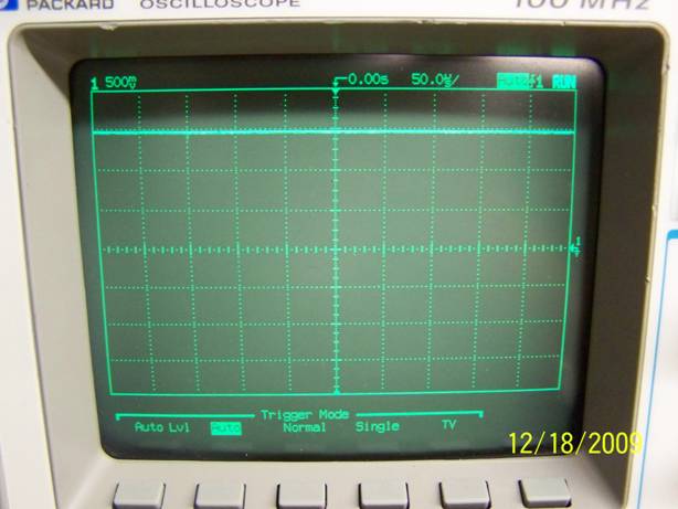
Figure 3: Point #2, the +15V Supply Input
for the 555 Circuit
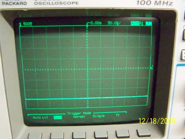
Figure 4: The -15V Supply at Point #4
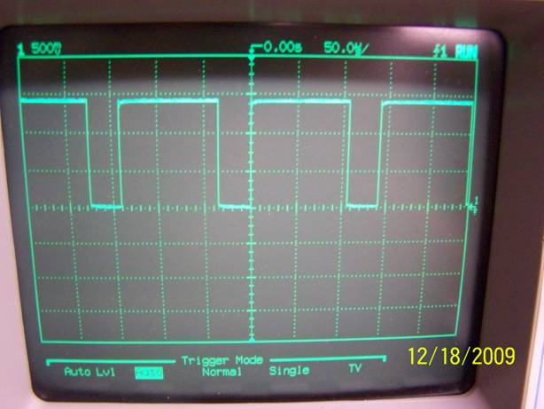
Figure 5: Point #3, Oscillating Output from
the 555 Circuit
There are other variations on the 555 circuit. One of them uses a line from the Sync Circuit as an input to the 555 RESET pin instead of an R-C circuit at the THRESHOLD input. But the result is fairly much the same sort of pulse train output.
The -30V power supply circuit might look a bit confusing at first but its operation is fairly straight-forward. The key to its operation are the blocking diodes. These allow current to flow in only one direction and block flow when reverse-biased. What follows is a sequential analysis of how the circuit works.
Figure 6 shows the same -30V power supply, copied here for convenience. At first we can assume that all numbered points are at 0V.
Figure 6: -30V Power Supply on Centipede
The circuit works sequentially like so:
1. Points #3,4,5,6 are at 0V. The -15V forward-biases CR5 and pulls point #5 to -15V. Incidentally point #6 also gets pulled to -15V through CR4.
2. Now the AC-coupling capacitor C86 acts kind of like a shock absorber in that when one side changes, the other likes to follow in the same direction just delayed and muted a bit. When the 555’s output at point #3 suddenly goes to +15V during its ‘on’ phase, the diode-side of the capacitor at point #5 tries to follow. As point #5 rises above -15V, diode CR5 is still forward-biased and point #5 is clamped and held at -15V.
3. After the ‘on’ phase, the 555 turns ‘off’ and the output at point #3 goes back to 0V. Point #5 then tries to follow. This time point #5 goes more-negative than point #4 and reverse-biases CR5. This causes CR5 to block current and point #5 drops 15V all the way down to -30V. Since point #5 is lower than point #6, CR4 is forward-biased and drags point #6 down to -30V as well.
4. When point #6 goes to -30V, the charge pump capacitors C84 and C85 together charge down to -30V. They both work together to supply negative voltage and current to the load device (the ER2055).
5. When the 555 goes ‘on’ again the output at point #3 goes to +15V again. Point #5 follows back to -15V. The cycle repeats with step 3.
As point #5 goes back to -15V, CR4 reverse-biases and holds the output point #6 at -30V. As the load (the ER2055) draws the supply current the charge pump caps C84 and C85 serve to ‘hold up’ the voltage to -30V until the next time point #5 pulls point #6 back to -30V. Figure 7 shows point #3 (the upper waveform) and the AC-coupled point #5 (the lower waveform). Note that the voltage scale was changed from 500mV to 1.0V to be able to show both waveforms.
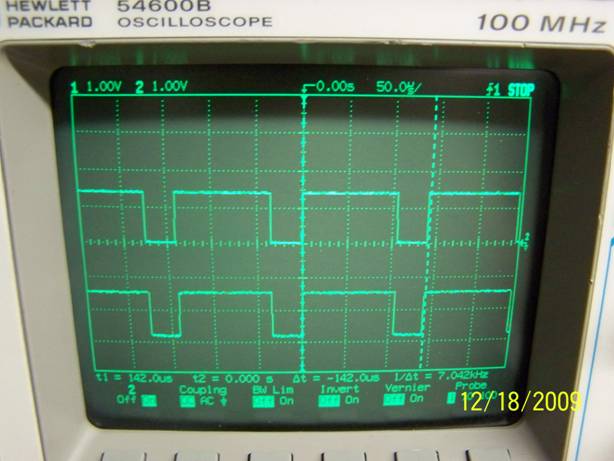
Figure 7: Points #3 (upper) and #5 (lower)
Figure 8 shows the resulting output voltage at point #6.
Figure 8: The -30V Output at Point #6
As you can see from Figure 8 the output voltage isn’t quite -30V. This is due mostly to the diode junction voltage drops associated with CR4 and CR5. These are approximately 0.6V each bringing the voltage closer to -28V. That’s ok because the ER2055 datasheet specifies that the difference between the programming voltage and the Vss input at pin 6 remain at -33V. With +5V at pin 6, the actual difference is indeed very close to -33V.
This concludes the analysis of the -30V power supply circuit. In Part 2 we’ll focus on the ER2055 itself and how it’s programmed.