Re-working Machine Pin Sockets
Of all the demons that haunt the test bench and torment both novice and
guru repair jockeys alike, machine pins sockets certainly are not lesser ones.
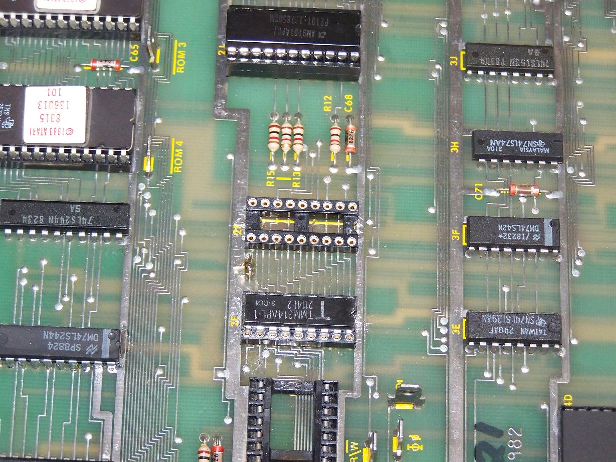
Seeing a dead board show up with one or more of these stuffed into a RAM or ROM
site will always draw a worried sigh from the repair stuckee. Ahh hell. But
fear not! There is a sound technique for exorcising these DIP-sized imps from
ruining your day.
The difficulty in removing a machine pin socket is two-fold. First, extracting
all of the solder from pins on the underside is nearly impossible. Typically a
good desoldering station is able to remove enough of the solder from a normal pin
to allow it break loose and slide free of the through-hole via. But because the
machine pins are relatively large, they act as very good heat sinks and require
much more heat to melt all of the solder holding the pin in place. Additionally
the way the socket-end of the machine pin sits directly on top of the via pad
makes it that much more difficult to suck all of the solder away.
The second facet to the puzzle is that machine pins are flanged on top
and prevent the plastic housing from being extracted from the top. But it is
this feature that we’re going to defeat to make extraction possible. But first
we need to prep the patient.
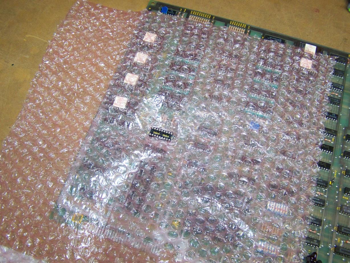
First size a piece of pink poly and cut a slit for the socket. We’re
going to grind down the top of the socket and we don’t want the debris going
all over the board.
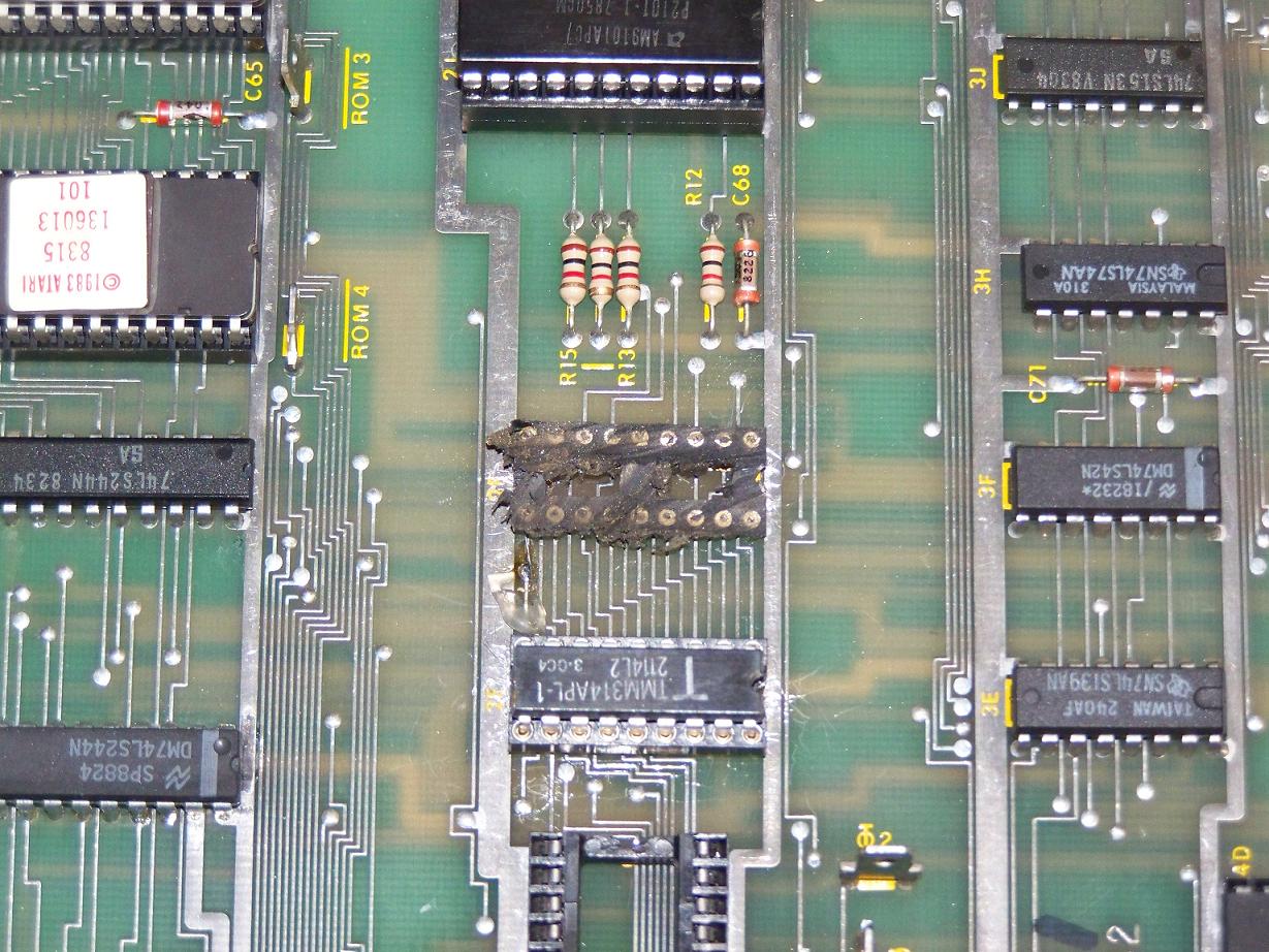
Next break out the Dremel and carefully remove the material on top of
each machine pin in the socket. The idea here is to remove enough of the flange
to allow the plastic housing to slip off freely. Be very careful not to contact
the board with the dremel wheel! Once all of the pin flanges have been ground
away, remove the poly and clean off any debris left over.
With the flanges no longer an obstacle, you can now carefully remove the
plastic housing from above. Carefully pry the housing up using a small
screwdriver with something to cushion the fulcrum point. Be very careful not to contact the board with the screwdriver!
Doing so will invariably mar the nearby traces and cause even more problems. Remove
all of the plastic housing.
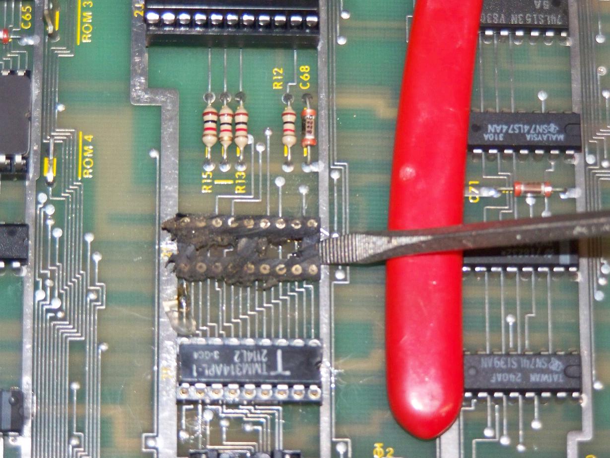
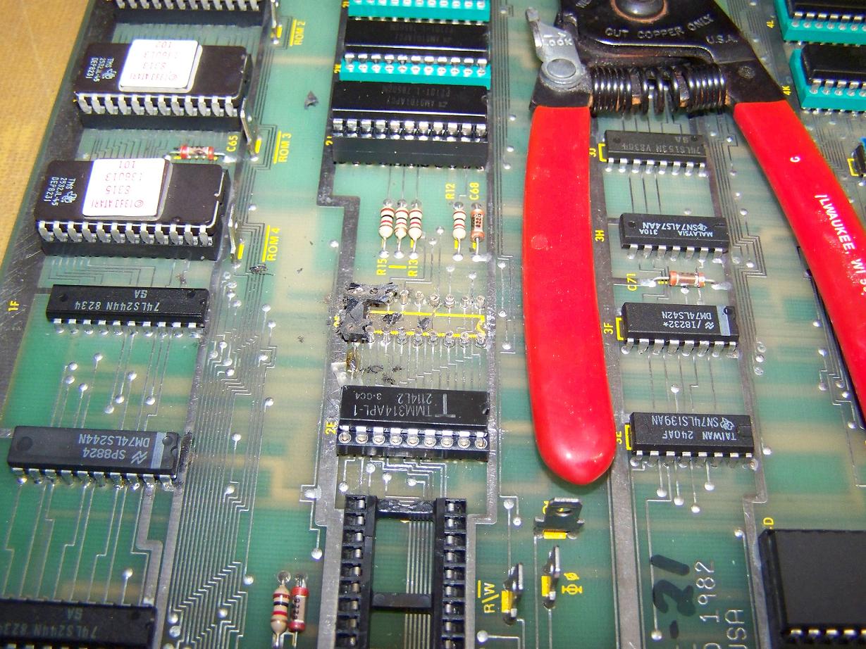
Now the pins are free to be extracted one at a time. So we put the board
into the vertical jig and with the soldering iron heat up the pins from the
solder side and carefully extract them from the component side.
Now that the pins have been extracted, we can use a generous amount of
flux and some solder wick to soak up the remaining solder from the vias and
pads. Lastly, apply some solvent and gently wipe away the flux residue.
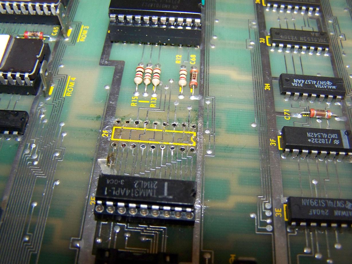
And viola! All cleaned up now. There is still much more work to do before
installing the proper socket. Many of the pads and traces have lifted due to
the previous repair attempt and will need trimming and shunts added. But the
patient will live!